Introduction
This post demonstrates the accuracy of CFD and the the insight that can be extracted by using a mixing tank as an example. Mixers are used in a wide range of industries from the chemical industry, oil and gas, waste water to food and beverage, each with varying process requirements.
Here we have simulated a Rushton turbine rotating in a cylindrical, baffled tank. The Rushton turbine is one of the earliest agitator impellers used and has been been investigated extensively experimentally and computationally.
In this blog post, we'll highlight some of the information that can be extracted from the simulations results with this impeller. Firstly, we confirm the accuracy of the CFD by comparing the predicted power number with measurements data in the literature. Then we show how deeper analysis gives insight that would otherwise be impossible and discuss briefly where this is applicable.
CFD Setup
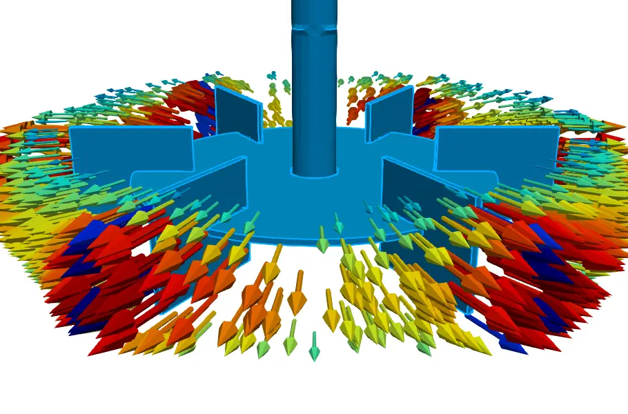
The Rushton turbine typically features six vertical plates fixed to a disk mounted to a shaft as shown in Figure 2. The actual geometry of the turbine is well defined as ratios of the diameter. Here, a 667 mm diameter turbine is located one impeller diameter off the floor in a 2 m diameter by 2 m high baffled tank. The baffles width is 1/12th the tank diameter.
Water has been used for the simulation. The liquid level has been modeled as a wall. This is done for simplicity, but is found to be a reasonably good approximation of a mixing tank.
A steady state solution is chosen for this simulation. A mixing tank by definition is highly transient, but when looking at the behaviour over long periods of time, average features become apparent which a steady solution is able to capture. Steady solutions also solve substantially faster and provide a good starting point for gaining insight and optimsations.

Turbine absorbed power and generated pumping
The power number is used to calculated the absorbed power of a mixer. The power number of the Rushton turbine is available in the literature and Bates et al. provides a power number of 4.8 which compares favourably to the calculated value of 4.68 from the simulation. Because there is a basis for confidence in the power results, subsequent results such as pumping or flow dynamics in the tank can be interpreted with greater certainty.
When analysing mixers and mixing tanks, the next impeller characteristic to determine is the pumping number. The pumping number can only be determined experimentally with specialised equipment such as laser-doppler-velocimetry and is more difficult to verify experimentally than the power number. Fortunately, extracting a pumping number is trivial in a CFD. Here we can compare our computed pumping number to results from the literature. Again the results compare well with a pumping number of 0.66 and 0.67 for the measured and CFD results respectively.
The agreement of the pumping numbers again gives confidence in the quality of the results that can be obtained from a CFD. It is especially relevant where new impellers are to be developed. Using CFD, the pumping number can be determined easily and quickly without difficult test work.
Velocity
Were we able to look into the tank on to a plane passing through the center, we would see a velocity profile as shown in Figure 3.
In this figure we can see the radial velocities generated by the impeller. This velocity is of the order of the impeller tip speed as is expected. On reaching the sides of the tank, the flow recirculates up the tank walls, assisted by the baffles. The arrows indicate the impeller is drawing liquid from above and below itself before being driven radially outwards.
The impeller is creating high velocities at the top where there would be a liquid level indicating vigorous surface movement should be expected.
It is very complicated to extract such an image from an experiment as this plane exists in the middle flow domain. To visualise this experimentally, one would need to be able to view through the rest of the flow domain. This shows the advantage of CFD, information about the flow can be evaluated throughout the domain.
.webp)
Can we do better?
Understanding the flow fields and characteristics of the equipment such as pumping and power numbers in the case of a mixer is important. These details are intuitive to understand and easy to visualise. Being able to verify the CFD against these measured values is extremely useful. Better yet, being able to predict these values once there is confidence in the CFD results.
But is it enough and can we do better?
CFD allows other useful additional information to be calculated and extracted that can be used to evaluate a configuration or process beyond what is possible to extract from test work. Some examples are shear rates and the total kinetic energy. These will be discussed below.
Turbulent kinetic energy
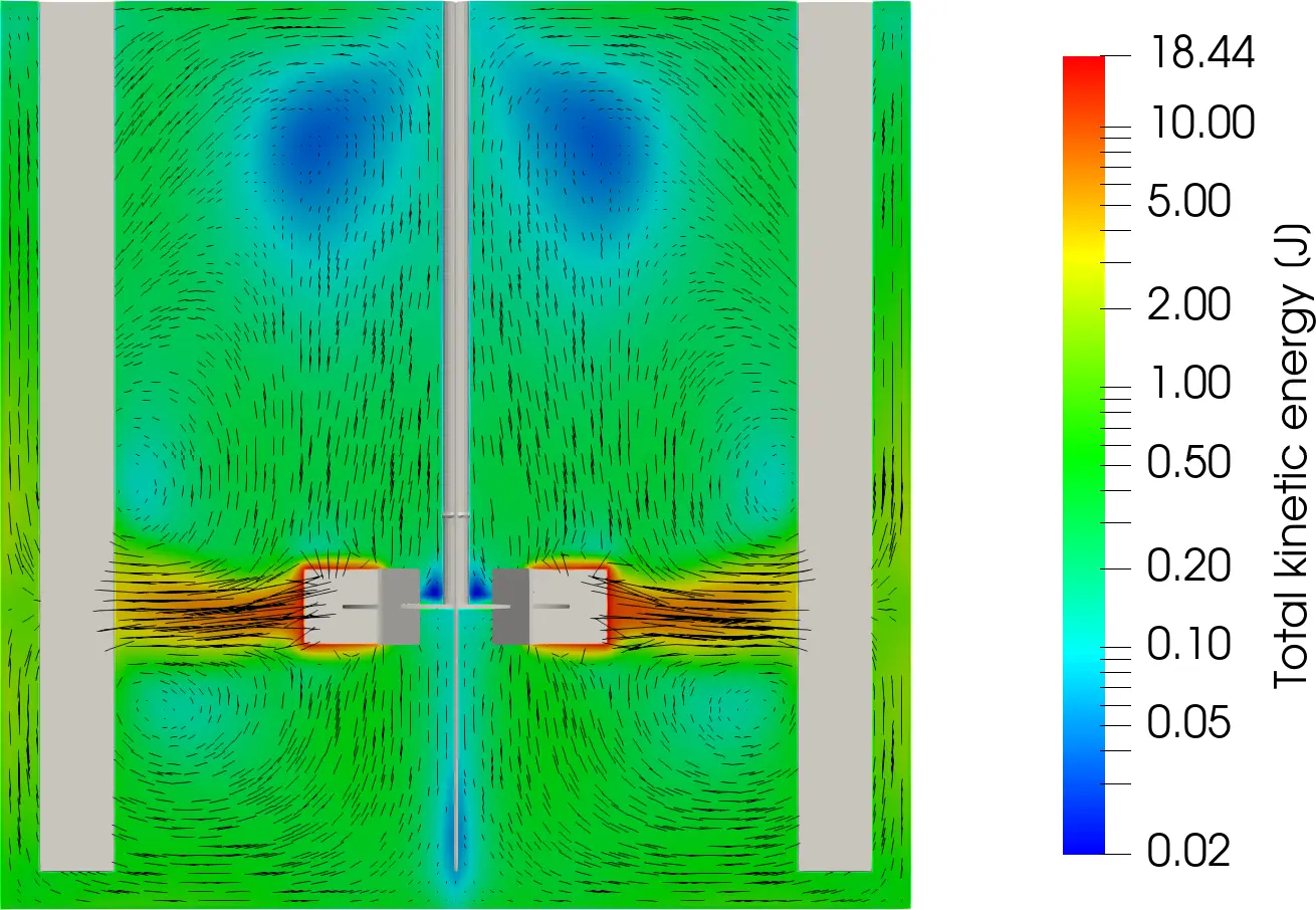
Visualizing the velocity field only reveals part of the picture of what occurs in the tank. The velocity of the fluid relates to the kinetic energy of the fluid due it convection through the tank. There is also however, turbulent kinetic energy which contributes a fluctuating velocity to the mean velocity presented above. The energy for this turbulent kinetic energy must come from the input energy into the system, in this case: the mixer. The turbulent kinetic is important because it is where mixing occurs. There are multiple ways to represent the contribution of total kinetic energy. In this case we have chosen to represent the total.
Higher values of total kinetic energy mean there is more mixing in the tank. In Figure 4, the total kinetic energy is high at the discharge of the impeller as expected. It is also interesting how most of the kinetic energy is concentrated in a relatively small volume of the tank.
Understanding the total kinetic energy can also be useful for scale up and scale down investigations. While many scaling factors exist, they are based on broad parameters such as power, volume and tip speeds, whereas equal kinetic energy may provide a better scale up/down parameter that matches closer to the process requirements at each scale. CFD can unlock alternative scale up/down insight that would previously be impossible.

Shear rates
Shear rates are important in mixing processes. Depending on the application, there may be minimum or maximum allowable shear rates. For example, bubbles would be broken by high shear rates which is desirable, whereas cell growth would be damaged by high shear rates.
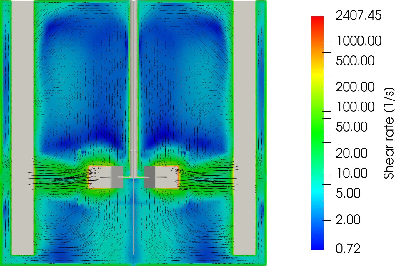
Figure 5 shows the shear rate which is calculated from the velocity field in the tank. As expected, the highest shear rates are generated at the impeller as this is where the highest relative velocities occur. Following this, high shear rates occur at the discharge of the impeller.
Extremely high shear rates occur at the impeller blade, but through the rest of the tank, shear rates remain lower. To understand the distribution, we consider Figure 6. Figure 6 shows the average and standard deviation of a horizontal slice across the tank. As expected peaks occur near the impeller, with subdued values throughout the rest of the tank. Understanding this distribution is useful for scale-up, comparing different impeller configurations or types and understanding overall mixer performance. This can lead to more effective installations and better performance of processes.
Being able to convert the visualisation of the shear rate in Figure 5 into an easily interpretable and comparable form such as Figure 6 is when CFDs become a powerful tool that unlocks understanding that can lead to improvements. Multiple simulations become easy and objective to compare, resulting in the best possible conclusions and decisions.

Conclusions
In this blog we have used the example of a mixing tank to show how CFD can accurately predict reality and how some of the experimental results that are difficult to obtain, can be easily reproduced using CFD. We then proceeded to show how the real value of CFD comes through in the properties that can be extracted that would be otherwise impossible to extract experimentally. This makes CFD an indispensable tool to complement test work, either in scale up or down or troubleshooting equipment behaviour.
If you have any questions, or would like to discuss how CFD could be of value to your process please contact us.